
Short answer / Facility
Choosing a fluorescence filter set means checking, for every channel, how much source light gets through the excitation filter and reflects off the dichroic mirror, and how much fluorophore emission then passes the dichroic and the emission filter. We built an open source app that does this spectral maths for any combination of source, filters, dichroic and fluorophore, so the check takes seconds rather than an afternoon of manual work.
We at CCA Bio are upgrading our microscopy system Tessera to do multichannel fluorescence. Multiple customers asked for it, so we started designing it.
Choosing the optical filters and light sources meant working out by hand how much of the source spectrum gets through the excitation filter and reflects off the dichroic mirror, then how much of the emission light passes back through the dichroic and the emission filter. I remember doing exactly that for FAM, HEX, ROX and CY5 when I was designing a PCR machine, and it was tedious.
So I built a tool. This short write up is also about vibe-coding my first ever web app. I have not written a single line of the actual code. It is a chronicle of an old dog learning new tricks. The app is published on Streamlit and open sourced under the MIT licence, so take it and adapt it if it is useful:
How a fluorescence filter set works
In fluorescence imaging the light the camera sees is not the illumination light, it is light absorbed and re-emitted by a fluorophore. That is the whole point of the method: the illumination is much stronger than the fluorophore signal, so the optics are arranged so that none of it reaches the sensor. The illumination is conventionally called the excitation light and the light given off by the fluorophore is the emission light.
A fluorophore is a molecule that absorbs light at one wavelength and re-emits it at a longer one. A reagent carrying a fluorophore is added to the cell culture to detect something specific happening inside the cells. Some fluorophores target DNA, some target specific proteins, some target metabolic processes. Which one you use depends on the experiment and on the scientists running it.
Every fluorophore has its own excitation and emission bands, and the light source, excitation filter, dichroic mirror and emission filter all have to be matched to it. There are two things to get right:
- The source light that survives the excitation filter has to be strong enough in the right band to drive emission from the fluorophore.
- The emission has to fall on the long-wavelength side of the dichroic mirror and inside the passband of the emission filter.
That is the entire purpose of the software tool. It makes those two checks quick. Other tools exist that do the same job, but I found them harder to use, so I wrote my own.
The optical system in Tessera
We image adherent cells on the bottom of an SBS plate, so the microscope is inverted. The rest is a fairly standard infinity space microscopy assembly.
The objective is an infinity corrected 10x/0.25 from Motic, chosen mainly for its price and its working distance. It has to reach through the bottom glass wall of the incubation chamber to the surface of the SBS plate where the cells live.
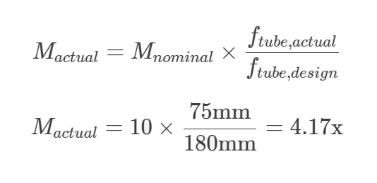
The tube lens is a Thorlabs achromatic doublet with a 75 mm focal length. The Motic infinity corrected system is designed for a 180 mm tube length, so a 75 mm tube lens reduces the nominal 10x magnification of the objective:
The imaging system is a Sony IMX412 sensor in an IDS Imaging USB camera. For a first prototype that looks like a poor choice: it has a Bayer mask and a pixel pitch smaller than the Airy disk. Both are deliberate. The Bayer mask lets us see whether any excitation light is leaking through, because leakage shows up in the wrong colour channel. A pixel smaller than the diffraction limit oversamples that limit, which confirms whether the optical stack is behaving as designed.
Going forward the camera will be switched to a monochrome version, probably with larger pixels, to collect light more efficiently and widen the field of view. How far we can go depends on how big an image the objective and tube lens combination actually forms in the image plane.
Fitting the filter cubes into the space available
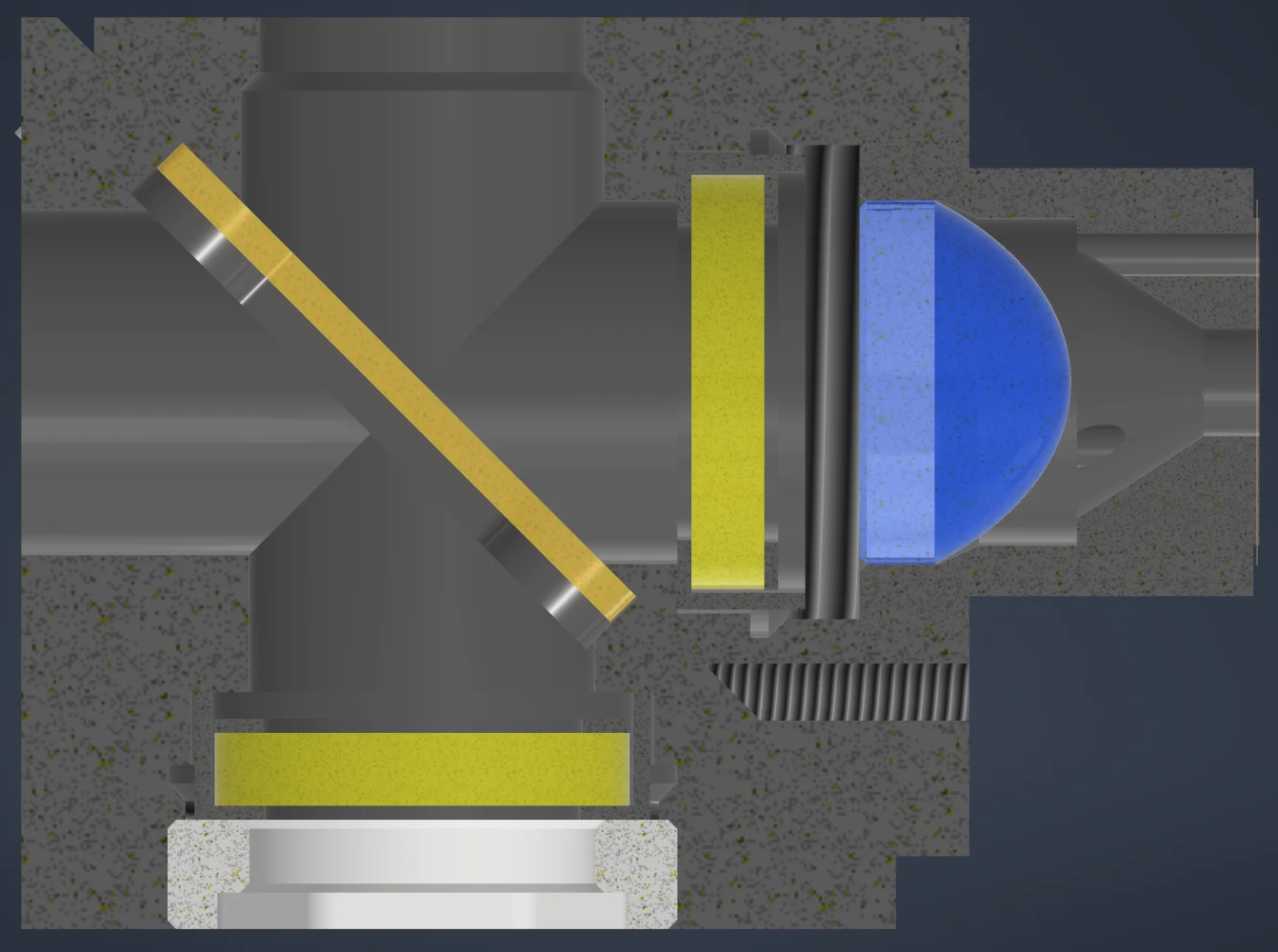
Cube switching is usually done on a rotary carousel, but we are very short of space, which is part of the reason we could not use even the smallest standard cube Thorlabs offers. At 40 x 40 x 36 mm it is far too big. The quality of Thorlabs mechanics is not in question, but I managed to squeeze the whole fluorescence filter stack into 26 x 25 x 19 mm.
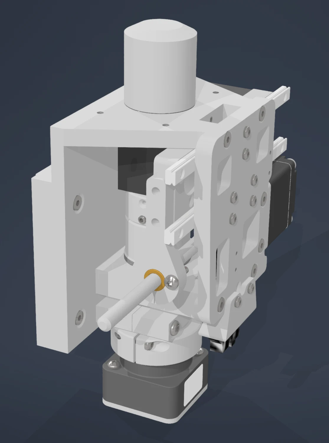
That let the filter cubes sit on a 20 mm pitch on a linear rail. Tessera already has a fairly comprehensive motion control system, so adding another motor axis was not a problem.
Where the build is now
I have just ordered the parts for the next iteration from the JLC CNC service. The first iteration needed some fettling because I forgot to account for the thickness of the anodising layer and a few parts did not fit each other. Other than that the assembly was an utter success.
Tessera is in early access. It sits alongside Pebble telemetry and the rest of the CCA hardware line, and everything it captures lands in CCA Labs against the sample and experiment it came from, so a confluence image is stored with the passage that produced it rather than in a folder on a workstation.
A version of this article was first published on LinkedIn.
FAQ / asked about this
Frequently asked questions
- What do the excitation filter, dichroic mirror and emission filter each do?
- The excitation filter narrows the source light to the band that drives the fluorophore. The dichroic mirror reflects that short-wavelength excitation light down to the sample and lets the longer-wavelength emission pass back through. The emission filter cleans up what reaches the camera so only fluorophore light is recorded.
- Why is the excitation light not visible in a fluorescence image?
- That is the point of the method. Excitation light is far stronger than the light the fluorophore emits, so the filter set is chosen to block it. If any of it leaks through, the image is dominated by illumination rather than signal.
- Can I use the fluorescence modelling app for my own microscope?
- Yes. It runs at fluorescence-model.streamlit.app and the source is on GitHub under the MIT licence, so you can fork it and adapt it. It is offered as-is with no warranty.